
One of the reasons I opted for the Peco Code 55 Finescale track was the availability of small radius points*. Although the Setrack points are actually a slightly smaller radius they're a wider angle so still take up more room. This was important on such a small layout.
*More properly in the UK they should be referred to as Turnouts but I've always called them points and will continue to do so. They are not called switches this side of the Pond - a switch is used to control electricity not trains!
I opted from the start to use DCConcepts Cobalt point motors as these seemed to be generally recommended. I don't regret that decision, although given the time and money I would have liked to experiment with alternatives! The main criteria I had in choosing was that they had to be under-board mounted, not too deep (I wasn't entirely successful there - see below) and slow-acting.
The alternative methods for lining up the motors are described in detail on the DCC website (clicky) so I won't go in to them here, but I'll describe the technique I used for the last couple of motors in the light of experience. If I was starting again I would certainly try the template method instead.
Based on advice on the forums I modified my point slightly by removing the spring. I believe this isn't essential (although I suspect it may interfere with the switching) but it's simply not required when using the slow acting motors since they will hold the blades over. I first tried this on one of my test Peco Setrack points and it was a disaster. The blades became so loose I couldn't see how it would ever work - at that stage I hadn't realised the construction is significantly different with the Finescale points! In any case it's a fiddly if simple job to do with a pair of fine-nosed pliers.
My understanding is there is no need to make any actual cuts to tracks, etc. with N Gauge points, however this differs with OO gauge. I can't comment on this! I didn't make any on my points and haven't notice any issues yet.
The track wiring was carried out in the same way as for the other lengths of track, with one wire from each of the outer rails on the point. An extra wire was soldered to the frog section of track. As with the other track-work I stuck to the colour coding system of Red wire to the outside of the layout, Black towards the centre. For the frog wire (which will be run to the Cobalt switches) I used red wire but added some black tape once it was installed to mark this.
Once the points were in the correct position (but not finally screwed down) I positioned the blades to the centre and drilled down through the hole at one end with a 1mm drill bit. Having lifted the points back out of the way I drilled back up again with a 5mm bit to create a reasonable clearance hole.
The next step was to install the activating wire onto the motor (not forgetting the securing screw) and centre the motor. I made up a very simple small electrical rig for moving the motors, consisting of a 12v plug-in PSU, a pluggable chock-block and a push button switch. The choc block will plug in either way round to switch the motor direction. You can do the same with just touching wires but I don't like bare wires on PSUs and this way gives better control.
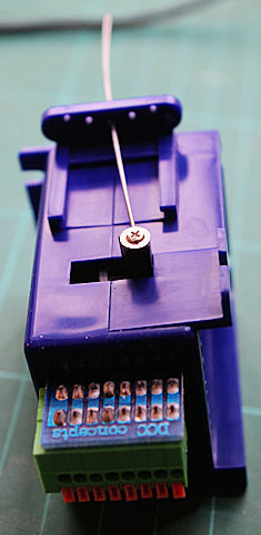
Assembled Cobalt - not a very straight wire with this one!
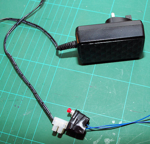
My DIY Manual Point Controller!
Once centred I put some sticky pad on top of the motor and then, through trial and error, fed the activating wire up through the point and centred the blades. A firm press up on the motor and hey-presto it's in position (that has taken a lot less time to write than do!) I then quickly drilled a couple of pilot holes and got 2 screws in to hold it all together before the sticky stuff gave way! Once I was happy with that I tested it in both directions. You can get a bit of extra throw if necessary by moving the slider down the motor - in a couple of cases I needed to do this to make sure the blades were sitting snugly on the rails.
The final stage was to wire up the motors as per the instructions. I'll be honest at this point. You could spend a lot of time trying to work out which way round the connections should go - I didn't bother! I worked on a trial-and-error basis. Once the point control wires are in place you can test if the point goes the right way for "on" and "off" on the controller - in my case I decided "off" means straight through, "on" means switched. Much the same applies with the frog switching - if you power up and have a short (you could even test with a meter beforehand) swap the wires and try again.
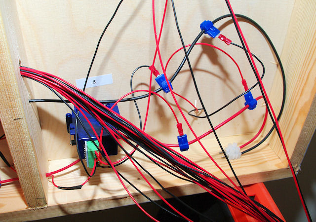
Point Motor 8 installed and wired
I had a couple of motors where the point blades were still in contact with the outer rails when the switch on the motor changed over, causing a short every time the point was changed. The only solution really is adjustment.
The absolutely last job - but only when everything is working - is to cut the activating wire down. Some day I'll work out a good way of doing this! It's quite tough and the large wire cutters don't really get it short enough.