
One of the issues with automating the railway is decoupling - detaching the stock from the loco. There are various ways of doing this, but for my purposes I decided the decoupling would have to be triggered by an electro-magnet (so it can be computer controlled). The next decision was which couplers to use. I've still not resolved this for the longer term but I've settled on a short term solution using Gaugemaster coupling adapters.
During the initial build phase most of my stock is quite old, and from a variety of sources. This tends to limit the replacement coupler options unless I'm prepared to do some quite fiddly modelling. I decided I'd save that for another day! This was also partly prompted by the release of magnetic couplings from Dapol - once I can get some of these (and it's likely new locos will come with them ready) I'll think again.
Having settled on this solution prior to a holiday I was quite fortunate to come across a model shop in Abergavenny that just happened to have the correct components in stock. That save a mail order purchase, at least for testing purposes. Once home I jury rigged the magnet to the accessory output on my Gaugemaster Combi DC controller and tried to attach the adapter to a coupling. Once I'd obtained some Loctite with a precision nozzle I tried again! This time the adapter seemed to stick OK.
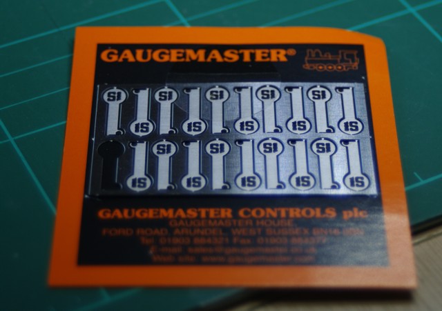
The fret of adapters

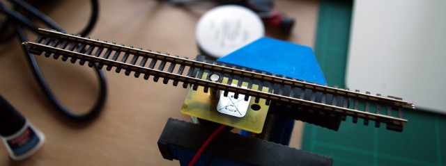
Adapter attached to coupling and bent to shape
A quick bit of work with the soldering iron then got the magnet connected and running for testing. I found that the coupling would lift effectively, but the magnet needs to be close to the top of the sleepers (in 00 gauge I think it will fit between sleepers, but not in N). There'll need to be some careful cutting to achieve this. The test version just has a hole drilled.
I wasn't too happy with the "fluttering" of the coupling from using an AC supply to the magnet. Fortunately as an IT Manager I have access to a collection of old laptop power supplies. A hunt through the box at work unearthed a 20v 2.5A DC supply. Once that was connected everything worked a lot better. This at least gives me the confidence to order some more magnets and start installing the track itself.
The next step was to work out how to control the magnets from the computer. There were two options here, I could use my non-DCC I/O board as I won't need anything like all the connections for detection or I could use DCC. I'd made an early decision to try and drive everything with DCC so that it could be manually controlled as well as via the computer. You can get relay driving DCC accessory decoders, however they aren't cheap and have power limitations. That left me with the option of using either a lighting decoder or a point motor decoder to actually switch relays. Either option would work but for sheer simplicity (and cheapness) I opted for a TCS FL-4 lighting controller which could do the job. These are really designed for mounting in a coach but I've mounted one on a piece of stripboard.
The circuit design (component side uppermost
Exactly what I've done is clearer on the photo...
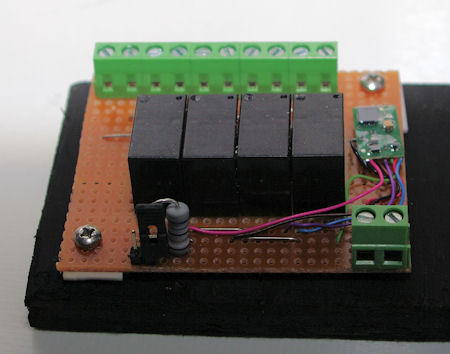
The resistor and jumper are included for programming - the instructions for the decoder specify a 50-100 ohm resistor should be inserted between the +12v and one control wire when using the programming track. This way I can simply close the jumper when required.
The plus side of this approach was cheapness - the decoder cost under £14, the remaining components less than £10 in total, so the whole board was under £24 compared to around £40 for a similar off-the-shelf item. The downside is that you are selecting it as a loco rather than as an accessory - personally I don't have a problem with this but the purists might!
To be Continued!