
For computer control to work properly you need to know where a train is or when it reaches a certain point.
DCC control means that positioning is fairly accurate for a given time period, i.e. if you drive a train for x seconds at speed y it will always stop at (or very, very near) point z. Unfortunately very, very near is not good enough for long term running - inevitably over several runs there will be some inaccuracy. If this is truly random it doesn't really matter, but the reality is that if you went backwards and forwards the train will almost certainly stop further and further from point Z.
There are 3 main ways of detecting a train, which I've described below. You then need to do something with the signal! For some this may just be an LED light on a control board, however for me it meant a computer interface.
From my point of view with the programming I only need to detect when a known part of a train reaches a certain point - once I know this I can time the next action for that train. Thus I could detect the loco itself, but equally I could detect the coach it's hauling!
There are various different one of these, both commercially available (such as the irDot range) and home built. The downside of these to my mind was the size of the hole required in the baseboard or, if mounted on top, the bits that would need to be hidden. They also aren't necessarily very cheap. I decided that these weren't for me.
These are small switches, often encased in a glass tube, which are triggered by a magnet in close proximity. They have the advantage of being readily available and fairly cheap. A bit of testing identified suitable switches and magnets. The switches will fit between the sleepers on Code 80 N Gauge track but may need a slight cut-out in the track bed on Code 55. The magnet is a small round neodynium disc magnet - this proved easy to attach to the bogie pivot on a railcar or coach, but not so easy on a steam loco.
These are designed to detect when current flows through a particular track section. Usually this would be when a loco enters that section, but could be a coach with lighting, for example. They are commercially available - I've got a couple of NCE ones for testing or they can be home-built. The NCE ones work by just passing the dropper cable to the track through the detector, simplifying the wiring considerably.
The main advantage of these is that you don't have anything above the baseboard at all. The only complication they introduce is the need to add insulating rail joiners to isolate the detected section.
I finally settled on using block detectors. although they are more expensive than reed switches they are simpler to install.
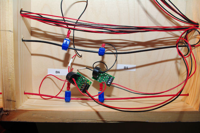
2 NCE BD20 Block Detectors
The above shows how easy the detectors are to install - just loop the dropper cable to the track through the detector. The only thing you have to be careful of is that the block sections are isolated from each other! Fortunately I found that the isolation from each point frog was perfect for my blocks, but if it wasn't I'd have installed some extra plastic fishplates. It should be sufficient to put the detector on one dropped in the section if there's more than one. Time will tell if this works OK. You'll notice in the above I've been meticulous in labelling things! The white tape on the droppers was to indicate the "detected" ones as I installed the track before I had the detectors. I've also labelled each detector.
When I first started developing the layout I couldn't use the NCE AIU for interfacing the detectors to the computer (since the PowerCab would only support one additional "cab" which was the USB interface) so I looked around on the 'net for an alternative. The board chosen was the Mirrorbow USB IO board. This provides up to 24 inputs and is reasonably easy to control via a virtual serial port. As always things move on! Mirrorbow no longer do the same board - they've moved on to other things and as of early 2013 the latest release of the firmware for the PowerCab will allow use of the AIU. At some point I'll get the updated PROM for the PowerCab and decide which way to go.
The Mirrorbow board does need further add-on electronics in the form of pull-up or pull-down resistors to prevent the inputs from "floating". These aren't difficult though and can simply be built onto perforated board. For testing purposes I built these on a small prototyping breadboard.
There are plenty of alternatives, however I have to say the Mirrorbow board was very competitively priced and their support when I was having problems with the programming was very good.
Basically if there is nothing at all connected to the inputs on the IO board they will "float", i.e. they may show connected or disconnected. To prevent this you normally connect the input to either +5v (to pull it up) or to 0v (to pull it down) via a resistor. Your switch then connects the input to the other supply connection. The resistor makes sure there isn't a dead short.
For practical purposes I've used pull down resistors, so the inputs are at 0 unless a train is detected when they will be at 1. I used a DIL resistor array for simplicity, but you could just as easily use separate resistors. Either 2,200 ohm or 4,700 ohm seems to work (2k2 or 4k7 as they're usually referred to). Any lower than 2k2 and you risk overloading the USB power supply, higher than 4k7 and it may not be effective. I've also used screw terminals to make the wiring easier. The outer 2 terminals at each end are the +5v supply for the switches, the centre 8 terminals are the inputs.
This is the rough schematic of the pull down board...
And the actual result...
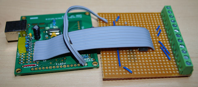
I spaced everything out more than on the diagram - space isn't an issue! What you can't see anywhere is that the tracks on the perfboard are cut under the chip (for obvious reasons).