As described elsewhere I had the layout fully designed in Corel Draw, although once I had the board ready I had to manipulate things to ensure none of the timber bearers interfered with the point motors.. The next step was to transfer this onto the baseboard. I apologise for the poor quality of the lighting on the photos below - I must rig something better as it's quite a dark room.
One option was to measure onto the board from the screen coordinates. It's quite possible to do this, but very tedious and there is plenty of scope for errors!
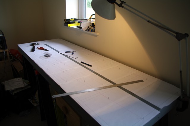
I opted for printing the layout onto paper (unfortunately as multiple sheets - I no longer have access to nice big roll-feed plotters). Having stuck the sheets together I located them onto the board and knocked fine moulding pins in at the key locations (the ends of straights, where the points go, etc.)
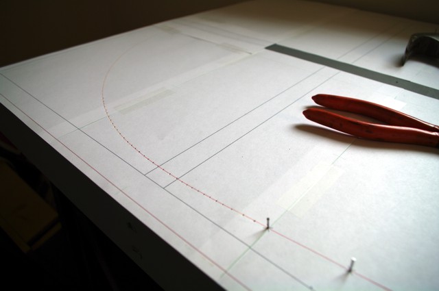
The next step was to mark the "free" curves at the end of the layout and to the bay platform in the station (see below). I did this by using one of the pins and just marking through the paper into the baseboard at regular intervals. This will be sufficient to lay the trackbed reasonably accurately.
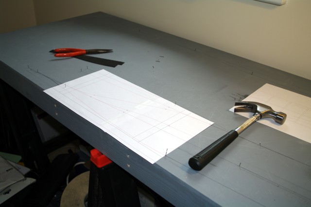
I also used CorelDraw to make up a template for the curves where the points are. This was printed onto a sticky sheet, stuck to a piece of modelling foam and cut out - ideal for drawing round! This is just about visible in the first picture.
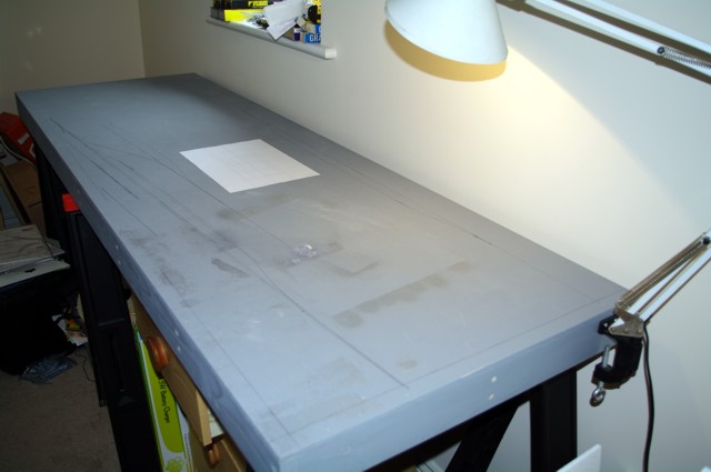
Once the original paper was removed I could draw in the straights with a long ruler against the pins and the curves using the template. At this point I discovered I hadn't marked the curve to the bay platform! Simple enough to print it out again and line up to the pins at each end.
And the final result is just about visible in this photo - along with various extraneous marks from earlier testing!