
My layout is relatively small so the wiring isn't too complex, however care is still needed to get things right!
Just how you wire the layout does differ slightly for DCC control compared to a "conventional" DC layout. You need to feed power to all parts of the layout at all times. It would be unrealistic to run lots of large sized cable everywhere, so practicality dictates a "bus" arrangement - run a thick wire around the layout and connect thinner cables from this to the rails. For Bishopwood the ideal thing to do would be to start at the end where the curve is and run busses from there in each direction following the track. Unfortunately with the layout in its permanent home this would put the connections at the wrong end! I decided that with the relatively small size I could get away with a single bus running from the main station area in a "U" around to the Halt. This fitted well with the pre-drilled holes in the baseboard framing however it's a good idea to separate the two bus wires by at least 100mm, although this isn't really necessary on such a small layout and using decent size wire.
Although the power requirements are quite low with an N gauge layout the distances can still be quite long. DCC does like a decent cable size, not for the power but to maintain a clean signal.
Having sorted through my stocks I found a couple of reels of 1.5 sq. mm cable left over from various car and boat wiring - checking various advice this seemed ideal for the main bus. The droppers from the rails to the bus, and the connections to the point motors, can be much thinner cable - I bought a couple of reels of 16/0.2 cable (0.64 sq. mm) cable for this.
One reason for buying reels of cable is that it's relatively cheap per metre - it's a lot easier to cut cables overlong and trim them down than to try and cut exactly to length so you don't run out of the expensive 10m you bought in the model shop!
This might seem obvious but whether using DC or DCC it's important to adopt a standard to ensure you don't get shorts. For me that meant using two different coloured cables. The red bus, and hence red droppers, are to the outside of the layout, the black bus and droppers are towards the centre.
All the pairs of wires running back from point motors, block detectors, etc. are labelled and correspond to idents on the layout plan. I used a small Dymo labeller, wrapping the tape several times round the cables. When I do have to remove anything I'll know where it needs to go back to! Even such a small layout has 8 point motors, 8 electro-magnetic decouplers and 6 block detectors, so that's 22 pairs of cables before we start.
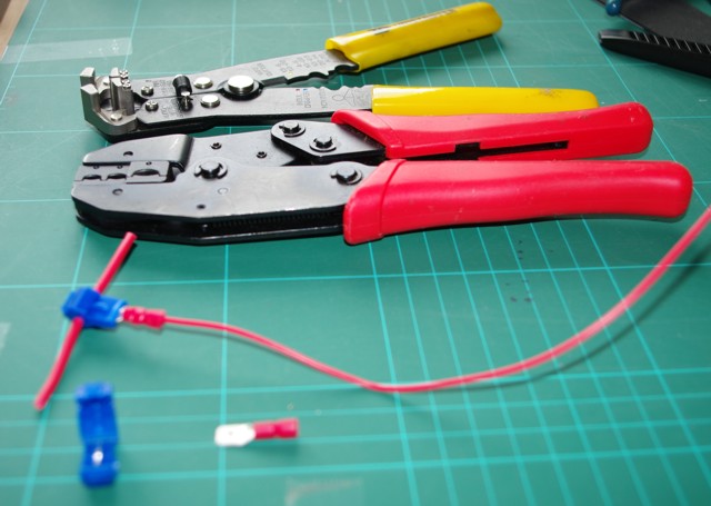
Most people's preference is to strip a section of insulation from the bus cable and solder the droppers to it - I have a couple of problems with this! The major one is the quality of my soldering, but it's also not easy to do while either crawling under the board or with it tipped up on its side. Sticking with the technical solution I opted for IDC connectors and crimp-on spades. These are available as model shop items, however they're much cheaper from electronics suppliers such as Rapid.
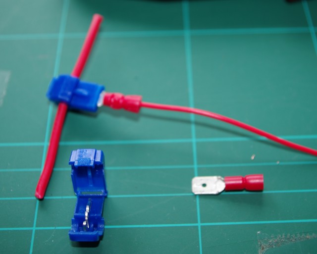
You need to make sure you use the correct connectors for the size of wire and I strongly advise anyone planning to use crimp connectors to by a professional grade ratchet crimp tool - the cheap ones you get in car accessory shops just aren't good enough for reliable connections. A decent wire stripper also speeds things up considerably.
In one or two places I had to lengthen the droppers, particularly from the point frogs to the point motor switches, for this I did solder the wires and then protect with heat-shrink sleeving.